Diode Boards & Grounding Wires On BMW Airhead Motorcycles
(including information on testing diodes)
© copyright 2018, R. Fleischer
http://bmwmotorcycletech.info/diodebds&grdgwires.htm
18
Basic and advanced diode board testing. Preliminary information:
Diode boards generally fail by having one or more diodes ‘open’ internally, “open’ means they do not exist electrically. Rarely do they short-circuit. There are small diodes on the diode board with two types of functions. Early boards, such as on the /5, did not have as many diodes as later boards, the later boards had a stator windings center-tap, which used the extra diodes to improve output wattage. Failure of any of the small diodes will cause strange output problems. Usually, a diode board failure is at the solder joint of one or more of the six large power diodes; or, that diode opens. It is quite rare to see shorted large diodes on the board. If a large diode solder joint becomes lousy or opens or the diode itself opens, the alternator will still produce current, but it will be quite considerably lower in total wattage output. The typical result of one large diode opening (or, solder joint failure) is that the battery will show near proper voltage during riding, but when the headlight is turned-on, the voltage will sag rather considerably.
Diode board testing and information about repairing the faulty Wehrle-manufactured ones (I’ve seen a few Bosch boards with the same problems with non-bent-over large diode leads and soldering failures) is covered in depth in the June 1999 issue of AIRMAIL, an article by the late great BMW Guru Oak Okleshen. Airhead owners may want to read the article. The Oak-recommended & difficult to do board modification could be done, with considerable effort, for reasons of solder joint failures, more likely if you have a R100 engine, which develops more heat (worse if an RS or RT). I’ve had good luck with a much simpler method, which is the removing of the ‘paint’ with gel type paint remover (often it has no effect though and abrasion is needed). I always enlarge the solder pad area first, whether the gel remover works or not, by careful scraping with a sharp Xacto thin blade hobbyist knife (don’t remove copper material), & then re-soldering using a high temperature solder (50-50 plumber’s solder and rosin flux) and a extra hot soldering iron. No re-painting or re-coating is needed, but certainly could be done. My repair method is vastly easier to do because drilling the PC board & adding wires & soldering per Oak’s method is quite difficult & best done by total disassembly, which Oak did not get into and is a huge PIA! Yes, it can be done with long tweezers or forceps, but that is quite tricky. I cannot recommend Oak’s method, and I won’t even do it myself. I’ve also seen several Bosch branded boards with this problem, perhaps Wehrle made them? There have been some other Bosch and Wehrle labeled products that made me think either could have manufactured them.
No matter the board maker’s label, I suggest inspecting the solder joints for overheating. More later in this article.
Testing diodes is most often done with a multimeter. Using the ohms function, voltage is applied by the meter’s internal battery. When this voltage is applied to a diode (if the polarity of the test leads are such that the “actual” – (minus) lead is connected to the end of the diode marked with a line (that end is called the cathode), then current can flow (conduct) through the diode. I am mentioning this as “actual” because many multimeters have – voltage on the + red lead on the ohms functions. The amount of current is limited by multimeter design. If the meter leads are then reversed, no current should flow (or, a super teeny current, called leakage current or reverse current). Thus, in the conducting direction, the resistance reading is very low, and in the reverse direction the resistance should be very high. Some multimeters have an extremely low voltage applied on the ohms function, and thus will not test diodes, because the meter can not ‘turn on’ the diode in the forward (conducting) direction, which requires as much as 0.75 volts on some small power diodes (most diodes will turn on between .4 and .7 volt). A few meters have both very low applied ohms functions voltage and a higher voltage application function. Some meters have a diode test function, & you do not then have to use the ohms function, unless you want to. I do both tests. The multimeter in diode test mode will indicate forward voltage drop of the diode. If the leads are reversed, you may get no reading; and, if so on the ohms function, you can get a ‘leakage’ reading, if using a very high ohms function range (if your meter has ranges, many are automatic).
Doing testing on a known good diode is a good way to get to know your meter. The most important readings are that the forward conduction be a quite low ohms reading, and the reverse be a very high ohms reading. For the Diode Test function, most such equipped meters read the forward voltage drop on the various power-rated diodes at ~0.5 to 0.7 volt, and if outside this range, the diode is probably bad.
Expanded and restated differently:
Diodes can be tested for forward current direction resistance on your ohmmeter and if there is no low ohms reading, reverse the test leads. The indication should be fairly low, and just about equal for all six power diodes on your meter. The diodes are in rows of three, the top row is reversed in polarity from the bottom row, so reverse the test meter leads. The actual reading could be 8 to 120 ohms perhaps, depending on the meter …the reading might even be a bit outside that on the X1 meter range (if meter has range settings). Most ohmmeters have an internal battery that enables “turning on” the diode under test, if the leads connection are in the proper direction. Some, usually expensive multimeters, do not turn on diodes on an especially low voltage ohms test mode and may have a higher voltage ohms range test mode for that. The reverse mode test of the diode should indicate a very high resistance and can be tested for this by reversing the ohmmeter leads to the diode & raising the full scale range setting on the ohmmeter (if it has manually operated ranges), & the reading should be in the millions. All Airhead diode board diodes can be tested in this manner. In fact, most diodes can be tested this way. Please note that ohmmeters (multimeters on the ohms ranges) can be ruined if the vehicle power is still on. To use an ohmmeter or diode test meter on a vehicle, it is mandatory to disconnect the battery. This is usually done by removing all the wires at the negative battery post …or, if only the one large wire, disconnect it at either end. DO NOT depend on disconnecting power from the diode board by unplugging the heavy gauge red wire spade connector at the right side of the diode board (facing from the front of the motorcycle)…do it at the battery!
If something else (besides the meter) is connected to the diode in certain ways, testing can provide poor information, or totally usable readings. Luckily, the ohmmeter test and the meter Diode Test functions both generally work OK on the Airhead diode board while it is still mounted and with its wires attached…. with some minor reservations. Better testing is done with the board removed and disconnected from all wiring, but it is not mandatory. In all instances, you must disconnect the battery before doing testing.
Unless you truly know what you are doing, do not apply the above tests (ohmmeter or diode test meter functions) to other diodes in the Airheads.
A better test method:
This is a dynamic test. It tests the diode board with some substantial, but safe, A.C current applied to the diode. This test works excellently, is quick to do, and provides information you can rely on, although I first do the ohmmeter test (and if available, the diode test meter function). This dynamic test is for all diodes on the diode board …but pay attention to the details below! Be sure you disconnect the battery. I vastly prefer this dynamic testing be done with the diode board removed from the motorcycle.
This dynamic test method is especially good for testing the six large diodes in the diode board. This tester, which you will build, applies A.C. current through the diode via one device, a lamp, that is both a suitable current-limiting and indicating type of resistance. If you stay under one ampere, this test is safe for even the small diodes of the diode board. Thus, I recommend two types of lamps be available.
Obtain two 12 or 14 volt lamps …a taillight run lamp (not brake lamp and not turn signal lamp) is fine for the small diodes, but you will want a more powerful lamp for testing the 6 large diodes …I suggest an old partly-burned-out headlight lamp, either an old 12 volt sealed beam type or any 55/60 watt (even to 100 watts) headlight lamp. You will also need a 6 to 12 volt transformer. Do not test the small diodes in the diode board with large lamps! A suitable transformer is Radio Shack #273-1352 (12.6 volts, 1.2 amperes) or, better, the # 273-1511 (12.6 volts, 3 amperes); or, appropriate other transformers. An old bell ringing transformer might be just fine. So also might be modifying leads for/on an old bulb type desktop high intensity lamp unit…maybe with its own lamp! Use of large lamps will draw the voltage down from small transformers, and burn the transformer out if left lighted for any longish period of time, but you will be using the setup only for moments at a time. The 3 ampere transformer safer in this respect.
If making from scratch you can purchase a socket with wires attached for tail lamps if you want to. Makes a neater setup, but not as neat as modifying an old desktop high intensity lamp unit. You can just solder wires to the low-power lamp section of a run/brake lamp if the lamp is the two-filament type. Nothing critical here….just do not pass over 1 ampere through the small diode board diodes.
The lamp must be the type that pulls a bit of current, and maybe half an amp to an ampere is OK for the small diodes. A few amperes or even more, is OK for testing just the 6 large diodes. I test the six large diodes using an old sealed-beam headlamp bulb (one side of which is burned out and I keep old two section lamps for this reason). You can get one from a wrecking/salvage yard from very old cars. I use a transformer of several amperes, it being ideal for the 6 large diodes and for the small diodes too.
This tester is worth the bother of making it.
Do not test the small diodes with the higher powered lamp. The brake lamp or section of the tail lamp that has the braking section, is not safe for the small diodes on the diode board. This caution also applies to turn signal lamps, which also draw too much current.
You can also make a two-in-one tester. Get a new run and brake lamp, such as the type 2257 or 2157, or 7528. These lamps have a TWO filaments, one is low powered (generally ~8 watts, maybe 3/4 of an ampere at most) for the run section; and 21 or 27 watts (roughly 2 amperes) for the high power brake section. The pins are offset, that is, staggered, so the lamp will plug into the socket (autoparts stores have sockets for them with wires) in only one direction. The high power section is OK to test the diode board big diodes, and the low power section is OK for testing the low power diodes in the diode board. You must identify the leads so you do not mix up the sections. You will have two wires from the lamp, plus the lamp shell wire. You use the lamp shell wire (make up a wire if not so equipped) and one or the other of the two lamp wires.
Common 55/60 watt 12 volt headlight lamps will allow about 4 or 5 amperes using a 12 volt output transformer.
With whatever lamp you are using, connect the lamp filament you wish to use in series with the transformer low voltage secondary winding, that leaves two wires for testing the diodes, one diode at a time. Use the sketch below. Note: The sketch calls out for a 6 volt to 15 volt transformer, which is correct. However, some old bell-ringing transformers are 18 volts rated. They will work OK.
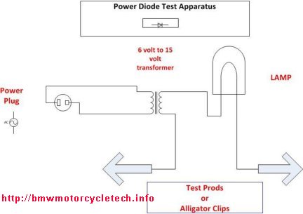
1. When the test prods from your transformer & lamp tester are touched together, the lamp will light up brightly.
2. It will be dimmed to roughly half that brilliance when connected to a good diode.
3. The lamp will not be lit if the diode is faultily open.
4. The lamp will be brightly lit with a shorted bad diode.
I suggest you make this tester into a nice shop tool. Get a set of test prods from Radio Shack. Make it your way, but do a neat job.
If you also do an ohmmeter front to back ratio test (disconnect battery in the bike!) then it is highly unlikely you will have any sort of diode faults that you did not find …..unless the diodes fail only at elevated temperature, which is quite rare.
Diode board mounts:
BMW used rubber diode board mounts on many models, from ~1979 to ~1993, with exceptions. Airheads that came with solid casting metal diode board mounts from the factory are: /5 models; /6 models; 1978-1987 R65 & R80 models. I believe BMW thought that installing rubber mounts would cure the problems they were having with the boards, which was actually not vibration which is what they must have thought, and why they used rubber mounts on some bikes. The problem, as earlier mentioned, was improperly formed & soldered leads on some diode boards, with the solder joints failing especially badly on fairing equipped models, and more especially on those if R100 models…all of which comes from from their extra heat. Additional factors were the lower flow of air through the early front alloy covers and the early non-louvered fairing centers.
Using rubber mounts meant that BMW needed extra grounding wires from the top (grounded side) row of diodes. Rubber mounts were poor at transmitting diode board heat to the timing chest casting (yes, I know about the minimal heat transfer at that point even by solid metal mounts). BMW’s grounding wire method did not work as well as solid mounts types did, electrically. This caused faulty voltage regulator operation, lowered output, wrong voltage, etc. The rubber mounts deteriorated, & if the diode board mechanically disconnected from the deteriorated mounts, sparks could fly, with resultant burned or otherwise damaged boards. The answer to all the problems from the rubber mounts are to replace them with solid metal aftermarket mounts, which have additional grounding benefits as well as lasting forever & they remove more heat from the diode board heat sink areas, which might add to diode board life.
Metal diode board mounts from aftermarket sources are not expensive ($15 or so per set of four). You could also make your own on a lathe. Do not use stacked washers and do not make them from stainless steel. Make the four mounts from 0.5″ aluminum or brass round stock. The “middle part” is to be 0.5″ diameter, 0.58″ (approximately) wide; and, each end might (read on…) have a threaded portion sticking out from that 0.5″ round piece. You could use a threaded piece of rod at each end, & thread the inside of the round piece, or, just make the entire piece on the lathe. If you use threaded rod, or a cut-off screw thread, use one drop of Loctite red on the threads on one end of each. Another way of making these would be to use an Allen screw (from the starter compartment side), and not have that particular end of the mount have a stud …only the other end…or, actually, you could have no studs (threaded material) at either end, just make the 0.5 x 0.58 piece, drill & tap it through; use Allen screws at both ends. Use Loctite red or blue at the rear, the starter cavity screw. The threaded stud, if you make or buy “all-thread” for its use, is 5 mm. You can certainly cut the head off a long screw for this. The best thing is to purchase four metal mounts from the sources I have listed below.
The following sources sell solid metal mounts for your diode board:
http://www.euromotoelectrics.com
http://thunderchild-design.com/homepage.html
also see: http://thunderchild-design.com/solid mounts-v2.html which has photos of one method of installation.
All mounts, rubber or the above all-metal aftermarket ones, are a bit of a pain to install. There are some tricks to it for the starter motor side of the mounts, and you really will be happy you put in 10 minutes installing the nuts or screws, and the modification is very worthwhile. Once you install metal mounts, you will not have to remove them ever again, never have to replace rubber ones, have longer diode board life; & you gain electrical benefits. This modification, if you have rubber mounts, is very worthwhile. I highly recommend that the new metal mounts not be tightened down in the front nor rearward areas until the diode board is pushed over the forward threaded area of the new mounts. Failure to follow this can result in a broken diode board mount area if you install the mounts first, and force the board on later. Tighten the rear screws or nuts, as case may be, tightly, and, you can, if you wish, use one drop of Loctite on the rear threads.
The grounding wires assemblies are a complex story in themselves:
HISTORY:
In September of 1988, BMW Service-Information bulletin 12-012-88 (2323) came out. It covered complaints of:
a) diode board connections having solder melting.
b) low battery charging rate.
c) GEN lamp would glow around half intensity.
That bulletin covered all boxer models from 1981 that had the electrostatic dip black coating on the timing chain case cover where that fits against the engine.
BMW said that increased resistance at the diode board grounding points, due to corrosion, ground wire connection deterioration; and, the exacerbating effect of the insulation from the paint at the diode board mounting points on the timing chain case, etc. were the causes. BMW’s fix was to remove the diode board & scrape away the paint from all 4 diode board mounts on the timing cover. Rubber mounted boards were to have the existing ground wires replaced if they looked corroded or overheated & those ground wires were to be soldered at their lugs. They also recommended cleaning the paint from the cover around bolt heads for the ground terminals, etc. I have seen many models after 1981 without that coating! Still, the bulletin does apply …as far as it went.
In October 1993, another BMWNA SI came out, this time it was 12-019-93 (2611). This bulletin supposedly covered all boxer models from 1980, except R1100 models (obviously, there were no R1100 models made yet, to say except to, for the prior bulletin). The date of models ‘from 1980’ is wrong. BMW made no mention of the 1979 model, which had the same setup, but the Bosch board was used. The Bosch-labeled boards mostly did not have the no-bent-leads problems…but, see earlier. Note, however, that it makes no difference about the boards here. The bulletin should have said 1979 onwards …and, the bulletin also forgot that BMW changed back the type of mounts in 1992 (I think it was 1992, some may have been later).
Well …that may be confusing, but that is OK, as quickly another bulletin supersedes that one. But, you will still need this second bulletin information, … so …here is the information for this October 1993 bulletin:
COMPLAINTS: diode board grounding wires getting hot, stiff, solder melting, melted insulation; alternator output falls below 13.2 volts.
CAUSE: increased resistance at the diode ground points due to corrosion of the ground wires and bolts.
REMEDY: install additional “ground wire” 12-31-1-468-013.
That “ground wire” is really a three wire ‘spider’ arrangement, one end of each connecting to a common lug. That means this harness has 4 lugs total. This entire assembly was to be installed such as to tie the diode board, timing case cover, and the engine housing, electrically all together.
The second page of this bulletin listed the above wire, a hex bolt 07-11-9-913-015 (an error, it really should be 07-11-9-914-148); an allen bolt 07-11-9-901-023 (should be 07-11-9-919-792); two washers 07-11-9-931-029 (see next paragraph); and finally, a ‘cap’ 46-62-1-453-668.
Regarding those 5.5 mm flat washers, number 07-11-9-931-029: I have seen only black colored washers. They do not conduct electricity well. That was fine, as they were in the kit for use at the lower, electrically hot from ground two mounts, & were to compensate for the thickness of the wire lugs of the grounding wires at the top mounts. The diode board fit over these lugs/washers/mounts. Under no circumstances use these black washers at the top studs, on the underside of the board, nor by mistake as a washer at the nuts. You may not even want to use these washers on the lower studs as specified in the kit instructions. The reason is a bit subtle & not easy to notice. All diode boards are not made the same, although they look similar, & I mean Wehrle versus Bosch; and, in some instances no matter what the brand on them is. Look at your diode board underside (rear side), & if the distance from the aluminum heat sink to the rivet end is the same for the two heat sinks, then you need the washers at the lower studs, they would go on first, before the board. If the lower, insulated rivets measure slightly more height overall than the grounded rivets, then just don’t use washers. You will need at least a vernier or something to measure the distance, as we are talking only a wee bit of difference. If using washers, get shiny metal ones. The standard BMW waverly washers are usually like that.
There was a sketch. I will describe where the connections are made, per BMW:
Facing the timing chest from the front of the motorcycle, the upper left & upper right diode board mounts were each a connection point for this ‘wire assembly’, & these wire connections were made onto the mounts.
Note! This is in addition to the already existing grounding wires at the top mounts, in the same position. Since there are now two lugs at each mount …this spaces the upper part of the diode board outward a tiny amount. The two washers in the kit were to be installed on the lower diode mounts to help equalize the spacing. See later note herein about those washers!
The hex bolt in the kit is used at the threaded area located directly below the large hole behind the diode board. The final connection is directly to the right of that …and the allen bolt in the kit is used there. This point is through the sort-of large elliptical hole in the timing chest…and this point where this last lug attaches is actually the inside engine case, the true ground. Thus, everything is tied together & grounded to everything else. It is important to note that it is this last connection through that elliptical hole to the threads already available, that makes the real grounding of the diode board to the engine itself; and this is an important connection.
NOTE: It is a good idea to use some grounding wires even if you have solid mounts, as the outer timing chest does not, because of painted joint surfaces, provide a perfect electrical ground to the engine. This is not something a simple ohmmeter test will show up.
In November of 1993, BMW came out with a revised version of S-I bulletin 12-019-93 (2611). Note that it has the same bulletin number(s). BMW also carried forward the same error not mentioning the 1979 bikes. In this revised bulletin BMW added some additional ’causes’ such as hot weather driving, city riding, low battery voltage, full fairings. BMW now corrected the parts numbering errors…and made some additional errors! …and, no, they have never fully corrected the ‘corrected revised version’.
The information on the wire harness & connections is correct as I outlined them above. But; the -792 allen bolt now comes with a captive waverly washer; and, the M6 ‘cap’ is not really needed …never really was anyway. You will, however, want to obtain a waverly washer for the -148 hex bolt.
The main reason I am having all this background discussion is that if you see something that looks strange in your timing chest outer area, you will know why …and if you see no such wires and you have rubber mounts, you will know of the modification(s). I highly advise you to install metal mounts if you do not have them. I also advise extra grounding of the two top diode mount screws, to the inner engine wall, as described, using a bolt in the threads located in the elliptical hole.
NOTE 1: There may be an existing M6 x 15 hex bolt with a waverly washer at the position of the true ground mentioned previously, so, use it!
NOTE 2: I have seen some very minor differences between some stock bikes ….maybe an extra washer found at a mount, that type of thing.
NOTE 3: If you have the solid aftermarket mounts, just about all in this mess of information is moot …except for the grounding wires, which may help charging, etc. Moot?….well……if the diode board fitting & mounts are clean of paint, corrosion, etc., …& the timing chest & engine are making good electrical contact (can be assured by adding a couple of grounding wires), …then this automatically ties the diode board grounding top area to the timing chest & engine case. I like to have one wire from the diode board grounding metal to a lug fastened to the bolt, threaded into the hole in the case, as noted. So, you do not have to purchase the BMW special grounding wires, you can make your own. The BMW ones are, however, convenient.
NOTE 4: It is likely that grounding wire 12-31-1-468-013 is no longer available. Remember that when entering a number on a dealership’s parts website, do not use hyphens.
NOTE 5: See http://bmwmotorcycletech.info/electricalhints.htm item #1, for additional information about the diode boards.
Problems removing & replacing the diode boards & mounts, tools, etc:
Removing the gas tank and then the starter motor area cover is obviously needed. Removing the starter itself is not necessary. Never remove the starter cover nor the front engine cover without disconnecting the battery first ….otherwise it is sometimes possible to short the starter solenoid terminal to ground, & cause serious sparks, or, similar for the diode board. Check the starter motor and solenoid nuts …they need to be tight & the big cable wire lug properly positioned so it won’t touch the starter area cover when that cover is replaced.
I have previously mentioned http://thunderchild-design.com/miscstuff.html. You may, or may not, find that ‘how to’ useful. But, there are numerous ways to remove the old rubber mounts and install aftermarket metal mounts.
The nuts used on both ends of the rubber mounts, or the forward end of cast-in-place mounts, or both ends of aftermarket metal mounts, require an 8 mm wrench. In order to do this job properly, you will want the following tools unless you are totally removing the inner timing chest casting:
A small combination wrench …open 8 mm wrench at one end; box wrench of 8 mm, preferably 12 point, at the other end. You can take an oxy-acetylene torch (or?) & bend this wrench to the shape needed. The bent wrench is to be used on the nuts on the starter motor side. Some folks have used a small 1/4″ drive 8 mm socket, & drive handle, etc., some modify those, some use a 1/4″ universal U-joint adapter in using that socket & drive handle. Whatever you want.
Do keep a tubular wrench of some sort in your on-bike tool tray, that would enable you to R/R the diode board, if it ever failed. You don’t really need any paticularly special tool to be in that tray for replacing the mounts …after all, you are now using metal ones.
An idea for a removal-of-the-diode-board tool, besides an 1/4″ drive 8 mm socket (perhaps ground a bit thinner) is as follows:
Obtain an 8 mm tubular wrench ….really just a tube incorporating a very small diameter socket at one end & a wooden or plastic handle, often generically called a SpinTite wrench. Harbor Freight has these in sets, cheaply, and calls them, properly, Nut Drivers. Be sure to get the Metric set. Grind the end of the 8 mm tubular wrench so its diameter is smaller, yet still strong enough. It is also nice to grind the tip end a small amount so no INternal taper is in the working 8 mm area.
Medium length hemostat: you may well want one, I like the curved type. I use mine for the installation of the washer & nut for the solid mounts (on the starter motor side of the inner timing chest) (or, for replacing the rubber ones with new rubber ones… if you are that stupid). Harbor freight has 12″ long hemostats (“locking clamp pliers”) for $7 or so, but they are not curved ….but they do have a 10-1/2″ curved type too ….and it will work fine. I think you will prefer one of these types of tools, rather than using offset long nosed pliers. Hemostat types of tools will enable you to start a screw, or nut, or washer, on the starter motor side of the timing chest. You may use a screwdriver to hold the nut against the threaded post, with help of the locking clamp pliers …or, whatever wrench/hardware you will have. I usually use such a tool to install the washer too, but some folks glue the washer, then the nut, to their fingers (Crazy Glue). I sometimes have used a steel screwdriver I have temporarily magnetized, to touch-hold the nut, while I try to get it started on the threads on the starter motor side of the mount.
When trying to install the nuts & washers for the solid mounts, they tend to fall down into engine cavities. They do not fall into the real insides of the engine, but may be out of sight in the cavity you will see. Thus, having a mechanics magnetic wand is a nice tool to have. You can get one at Harbor Freight. This is one of the reasons for folks gluing washer & nuts to fingertips, tools, using of small magnetized screwdrivers….etc! There is always a chance of some hardware falling ….and the magnetic wand is very handy…so, get one! There is also a grabber type tool on a wand, but I find it not useful for this cavity area.
For metal mounts, I recommend that you not only use shiny metal waverly washers on the inside starter motor side, but also have a wee drop of Loctite blue on the threads.
A proper and correct circuit sketch is below. One sketch, somewhat similar, was published at http://www.buchanan1.net/charge.html but that sketch has errors! Do not use that buchanan1.net sketch, nor his page. Long ago I had a corrected version of Buchanan’s in one of my articles via link. I removed it, gave up trying to get him to fix his. As of 11/07/2017, my most recent check, Buchanan’s errors were STILL not fixed, after many years of him knowing about this. His sketch, similar to the one below, is not correct!! Use my corrected sketch, below!
The following sketch originally came from http://www.thunderchild-design.com/images/charg1.gif. The sketch “was” similar, but not the same as Buchanan’s. I have considerably modified Thunderchild’s sketch, just below, with identifications of wire colors, small diodes, current flows, and /5 system information. The only items I have not put into this sketch are the Kill switch, and the later /5 system’s fuse in the charge light circuit. Arrows show direction of current flow.
When the engine is started the rotor is rotating as it is fastened to the end of the crankshaft. The rotor’s rotating magnetic field induces a magnetic field in the non-moving stator windings. Thus, rotor magnetic field is transformed into Alternating Current electricity in the non-moving stator windings. Certain small diodes on the diode board change the A.C. electricity into Direct Current electricity, which is then applied to the same input side of the voltage regulator that the GEN lamp feeds. With enough rpm to have approximately +12 volts at that point, the lamp extinguishes, as it has approximately +12 volts on one side of the lamp (from the battery), & approximately same +12 volts on the other side of the lamp, & thus no voltage difference across the lamp. These small diodes, as rpm increases, produce a VERY considerably larger current than the lamp could supply to the regulator. That larger current is needed to fully power the rotor. Thus, the system can be thought of as a merry-go-round, supplying itself, once initiated by the battery-fed lamp current & enough rpm to produce enough current from the small diodes. The system converts mechanical movement into usable electricity.
Revisions:
12/05/2017: All prior revisions incorporated. Layout improved; HTML lessened; colors and font changes greatly reduced. Edited and placed on airheads.org website
© copyright 2018, R. Fleischer
