In This Issue:
Message from the Board
Head to Head
Club Canon 8
Perspective: The Airhead Story
Wrenching: Adopting a 1984 BMW R80RT
Airhead Interview: A Lifetime of Riding: Sitting Down with Rex (Dezert Dog) Mangold
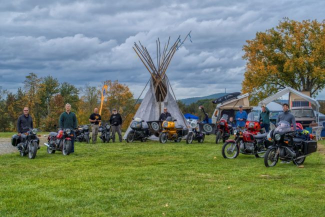
Rendezvous: BMWs at the Black Bear Americana Music Festival
The Ride: Birds of a Feather
Perspective: Appropriate Repairs – Inappropriate Places
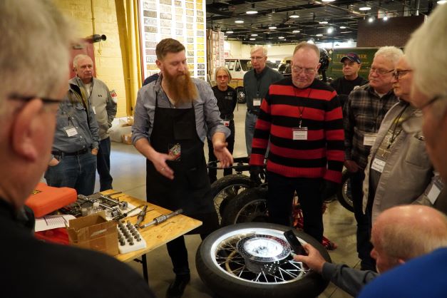
Workbench: Replacing Steering Head Bearings
Upcoming Airhead Events
Airhead Marketplace
Airmarshals Directory
Join The Airheads
Airstore